Lets talk about quadrature decoders and how to create one with verilog HDL. As with most things programming related there is more than one way to accomplish this. Some implementations are smaller than others, however some more concise implementations can be hard to understand when reading the code. You can make them with the bare minimum of just a register to hold the count value or more sophisticated by adding current speed as well and pretty much whatever you like. For now I just need something simple that can count the edges of the signal, either up or down depending on the direction of travel.
I will be using this quadrature decoder for controlling a robot so it needs to have no errors when direction reversal happens.
The quadrature decoder needs to be able to correctly handle all eight possible direction reversal cases, shown below, without error.


Quadrature Decoder Verilog
Below we will be looking at two examples of creating a quadrature decoder with Verilog. The first uses a Finiste State Machine based approach and the second is size optimized, however as you will see the size optimized implementation is hard to understand when looking at the Verilog.
FSM based Quadrature Decoder
We can quickly draw up a state machine to visualize how the states relate to each other. Thankfully as far as state machines go this one is simple. By the very nature of how the A&B channels relate to each other each state has only two possible paths and the next-state to which we change also points to the direction of rotation.

You can read a very usefull paper from Xilinx on the Mealy and Moore state machines and how to implement them here Moore and Mealy FSM.
Ok, enough talking, here is a quadrature decoder with syncronous reset that uses an FSM based approach. The states are represented as S00, S11, S01 and S10. It uses 64 LUTS and 38 Registers on a Spartan 7.
module Quad(
input clk,
input reset,
input A,
input B,
output reg signed [31:0] count
);
(*ASYNC_REG="TRUE"*)reg[1:0] sync, AB; // synchronization registers
reg[1:0] state;
localparam S00=2'b00, S01=2'b01, S10=2'b10, S11=2'b11; // states
always @ (posedge clk) // two-stage input synchronizer
begin
sync <= {A,B};
AB <= sync;
end
always @(posedge clk) // always block to compute output
begin
if(reset) begin
state <= S00;
count <= 0;
end else
case(state)
S00: if(AB == 2'b01) begin
count <= count-1;
state <= S01;
end else if(AB == 2'b10) begin
count <= count+1;
state <= S10;
end
S01: if(AB == 2'b00) begin
count <= count+1;
state <= S00;
end else if(AB == 2'b11) begin
count <= count-1;
state <= S11;
end
S10: if(AB == 2'b00) begin
count <= count-1;
state <= S00;
end else if(AB == 2'b11) begin
count <= count+1;
state <= S11;
end
S11: if(AB == 2'b01) begin
count <= count+1;
state <= S01;
end else if(AB == 2'b10) begin
count <= count-1;
state <= S10;
end
endcase
end
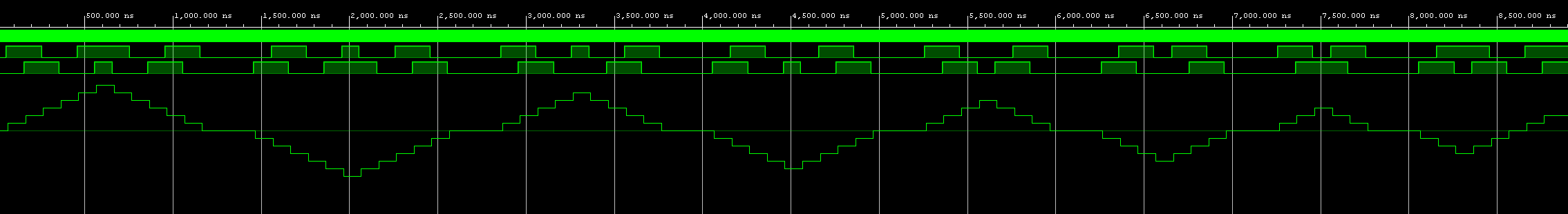
endmoduleCode language: Verilog (verilog)And here is the simulation waveform for this quadrature decoder module showing all direction reversals being handled correctly.
Compact Quadrature Decoder
We can accomplish the same thing with this more compact version, this implementation uses nearly 50% less LUTS at 36 LUTS and 38 Registers.
module Quad_compact(
    input clk,
    input A, input B,
    input reset,
    output reg signed[31:0] count);

(*ASYNC_REG="TRUE"*)reg[1:0] sync, AB; // synchronization registers
reg[1:0] os; // old state
wire[1:0] tmp, ns/*new state*/;

always @(posedge clk) // two-stage input synchronizer
    begin
        sync <= {A,B};
        AB <= sync;
    end

// OR signal[0] with signal[1] - creates pulses on every edge of quad signal
assign tmp = {AB[1],AB[1] ^ AB[0]};

assign ns = tmp - os; // Get new state

always @(posedge clk)
    begin
        if(reset) begin
            count <= 0;
            os <= 0;
        end else
            if(ns[0] == 1'b1)
                begin
                    os = os + ns; // set current state to old state
                    if (ns[1] == 1'b1) begin
                        count <= count - 1'b1;
                    end else begin
                        count <= count + 1'b1;
                    end
               end
    end
endmoduleCode language: Verilog (verilog)
In a future post we will look at adding some more functionality and also how to prepare this module to be used in the Vivado IP integrator.