Table of Contents
Introduction
In this PicoRV32 Vivado IP Integrator project we will use an PicoRV32 IP we created, HERE with the IP packaging tool in Vivado. I am using the Arty S7 with the XC7S50 part on it. We will use this IP to create a block diagram in Vivado and build a full system. We will also make use of the XIP (Execute-In-Place) functionality of the AXI Quad SPI Peripheral so we can store our code on the external flash drive.
Lets get started
Create a new project with Vivado and select the particular FPGA part you are using. I am using the Arty S7 dev board from Digilent so I added the board files to Vivado and selected the board while creating a new project. This means that Vivado will automatically make the components on the Arty S7 available to me for use in the block design. There are plenty of resources online on how to add board files to Vivado so I won’t cover that here.
In the left-hand navigation pane select “Create Block Design”, I chose to call mine “system”
Add the PicoRV32 IP to the Project
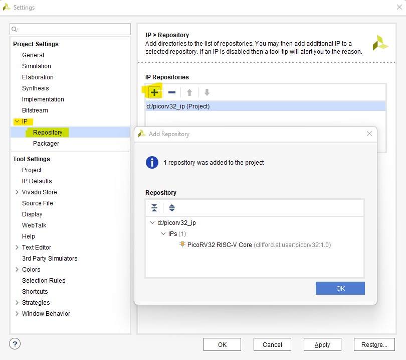
Add the PicoRV32 IP from HERE to the project by going to Settings -> IP -> Repository and then add the folder.
Configure PicoRV32
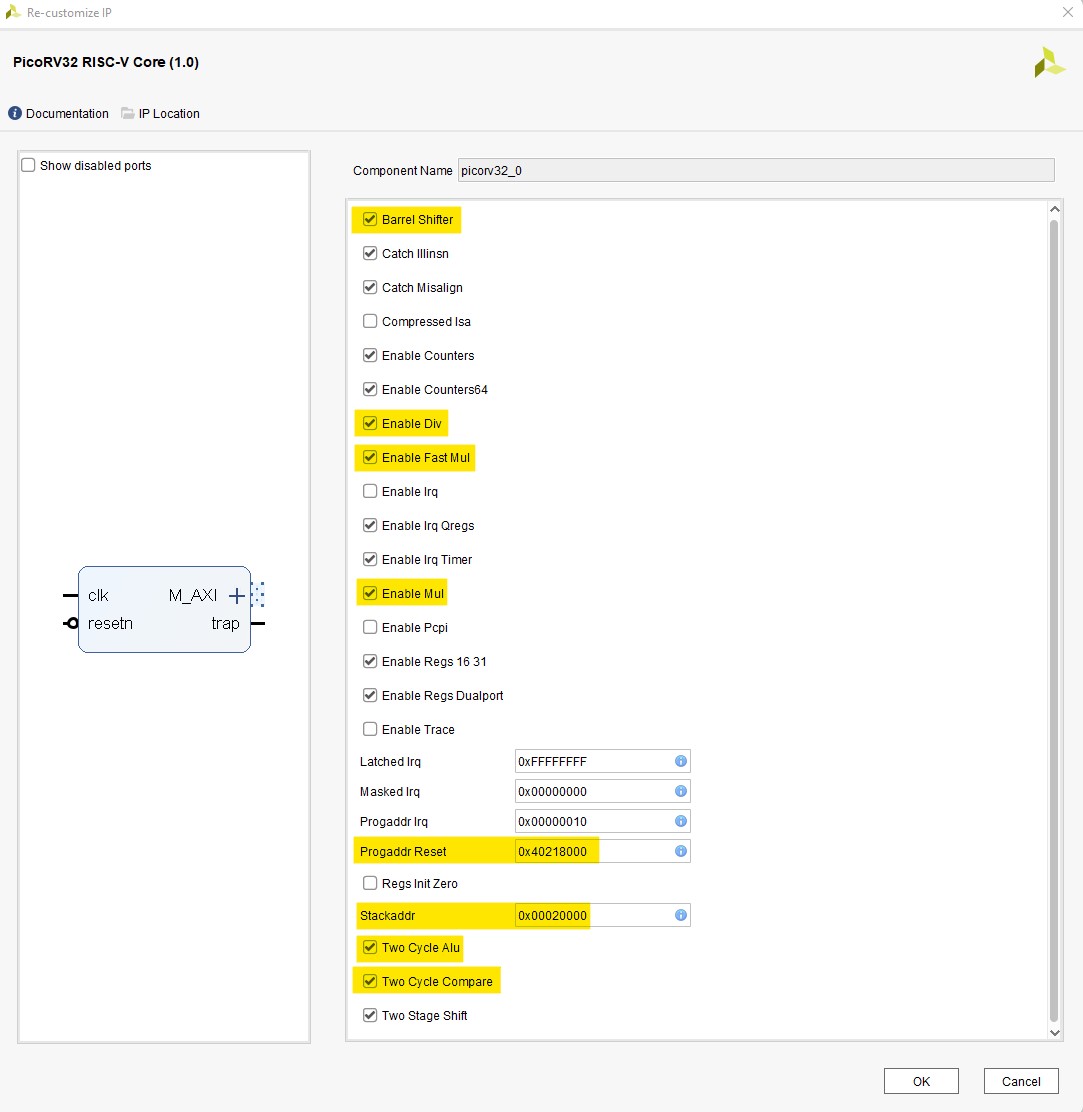
We need to enable some features of the PicoRV32 and also set the start-up and Stack address. All the options I changed are highlighted in the picture to the right.
System Clock
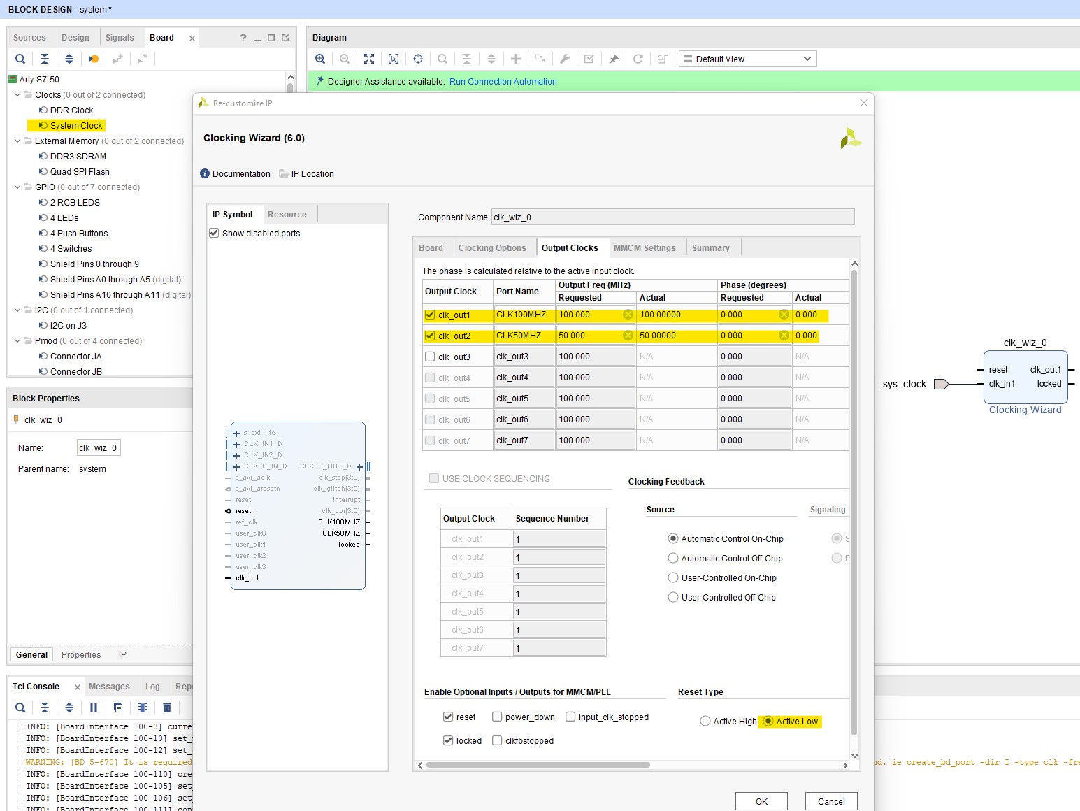
Drag the “System Clock” component onto the canvas and double-click on it to configure it. Go to the “Output Clocks” tab and add another clock. Set the 2nd clock to 50 MHZ. I changed the names of the two clocks to something that I can identify easier later on. Also change the “Reset Type” to “Active Low”
AXI QUAD SPI
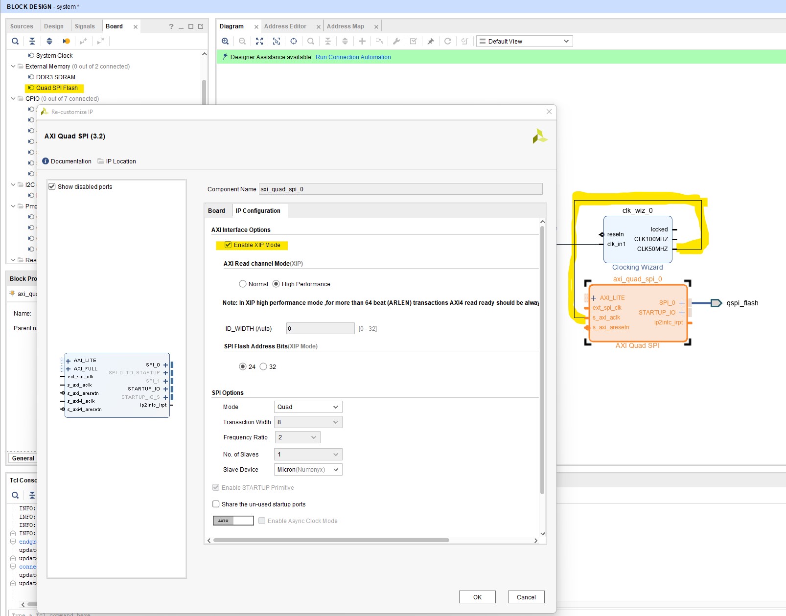
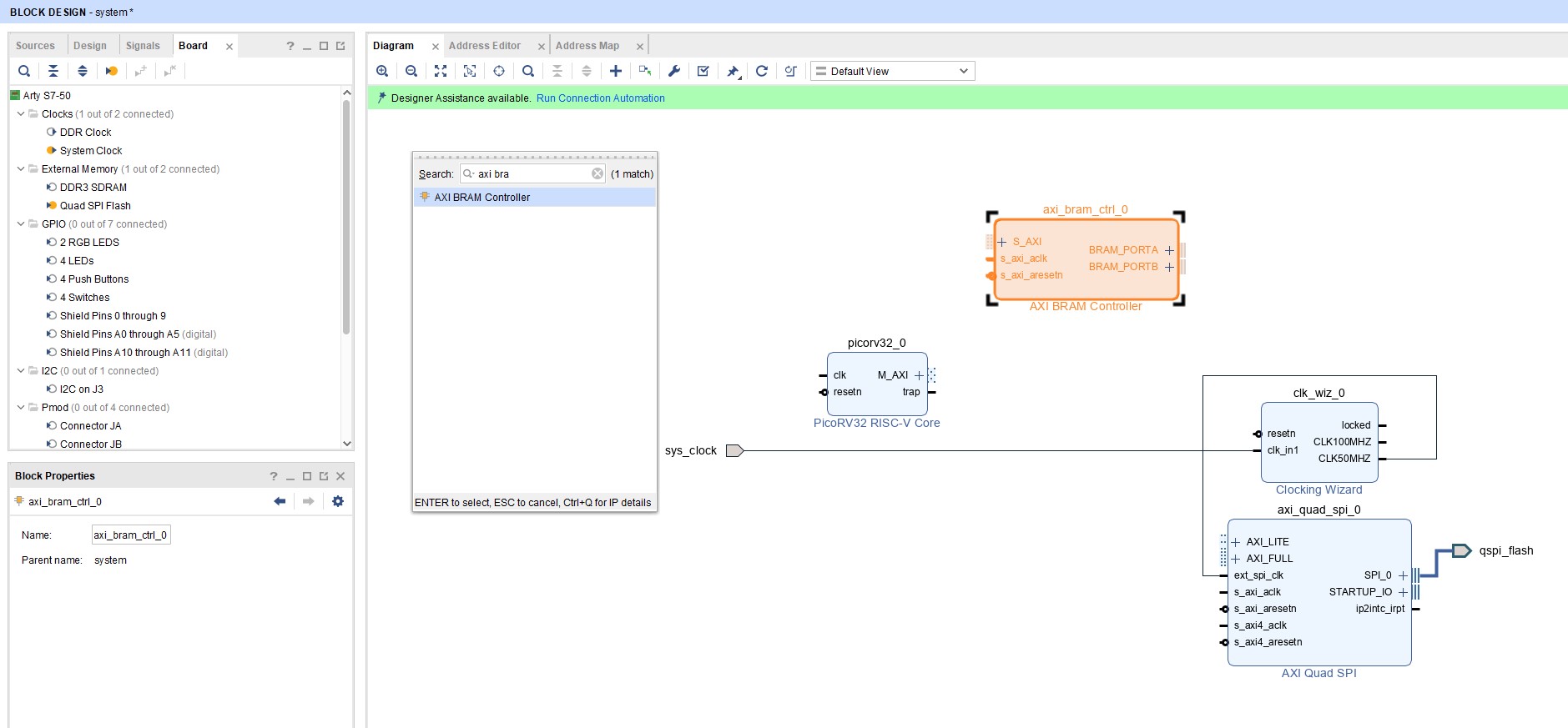
Drag the QUAD SPI Flash component onto the canvas. Connect the 50MHZ clock from the clock wizard to the “ext_spi_clk” pin. Double click the component to open the configuration dialog and go to the “IP Configuration” tab. Tick the “Enable XIP Mode” box.
AXI BRAM Controller
Add a AXI BRAM Controller to the design.
LEDS & Push Buttons
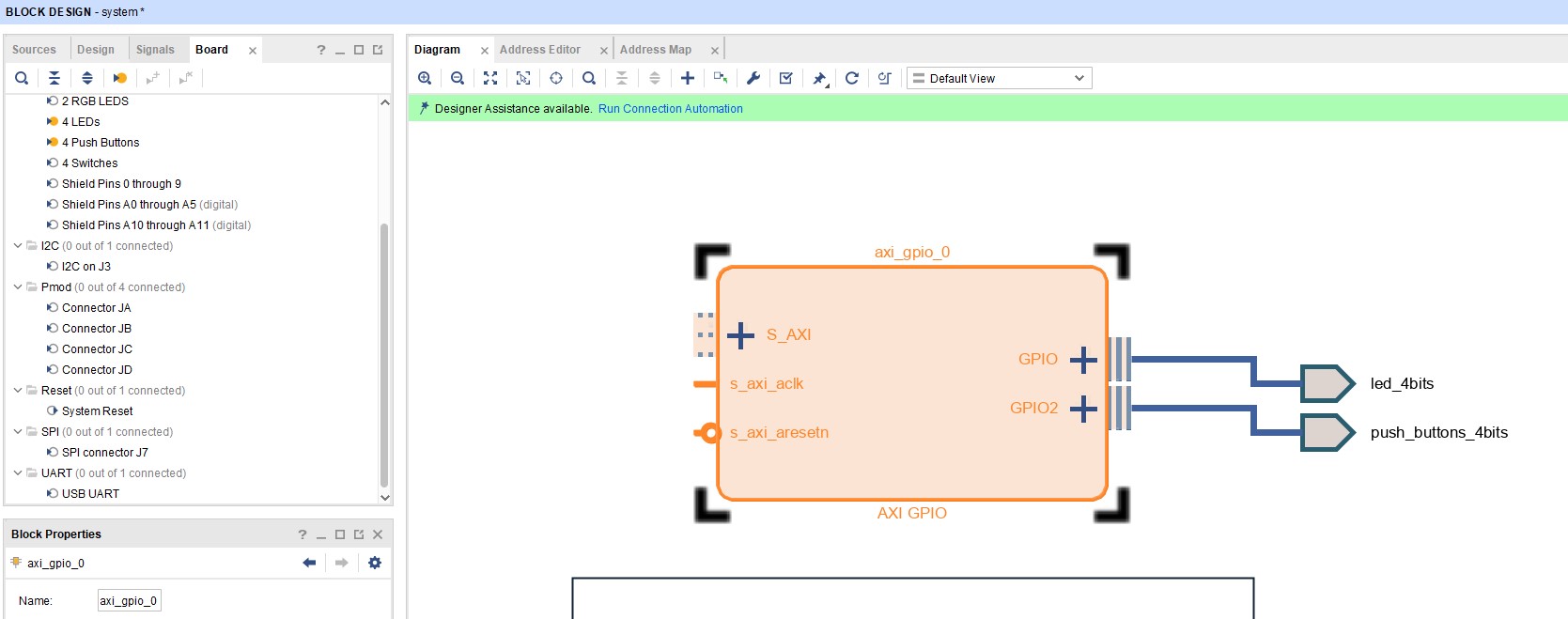
Drag the 4 LEDs and 4 Push Buttons components onto the canvas.
NOTE: Ensure LEDS are connected to “GPIO” and NOT “GPIO2”. Ultimately it doesn’t matter, as long as you account for this in software.
Processor System Reset
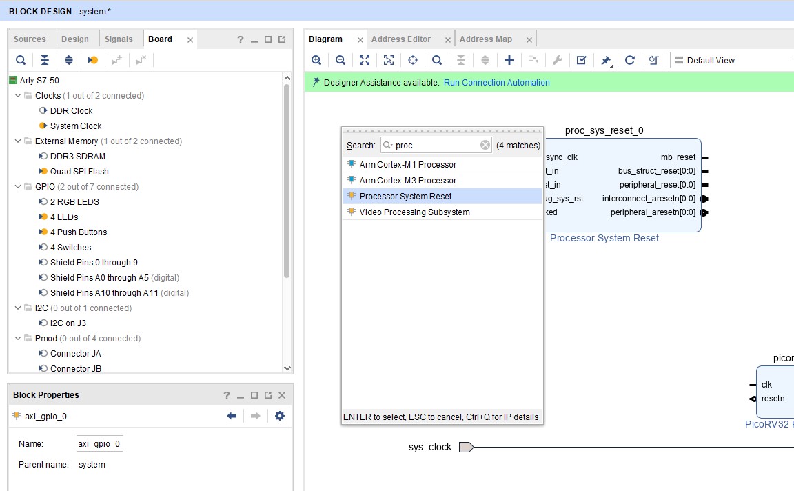
Add a Processor System Reset to the design
Utility Vector NOT
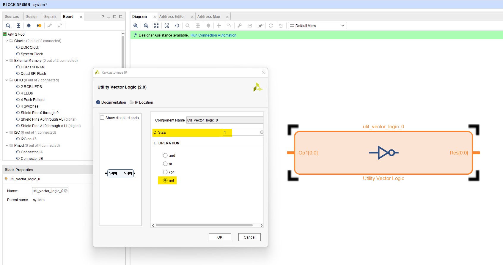
Add a “Utility Vector” component to the design. Double click on the component and configure it with a “C_SIZE” of 1 and a “C_OPERATION” of “not”.
Connect Processor Reset to PicoRV32
Connect the PicoRV32 “resetn” pin to the “mb_reset” pin of the “Processor System Reset” component through the Utility Vector in order to invert the signal
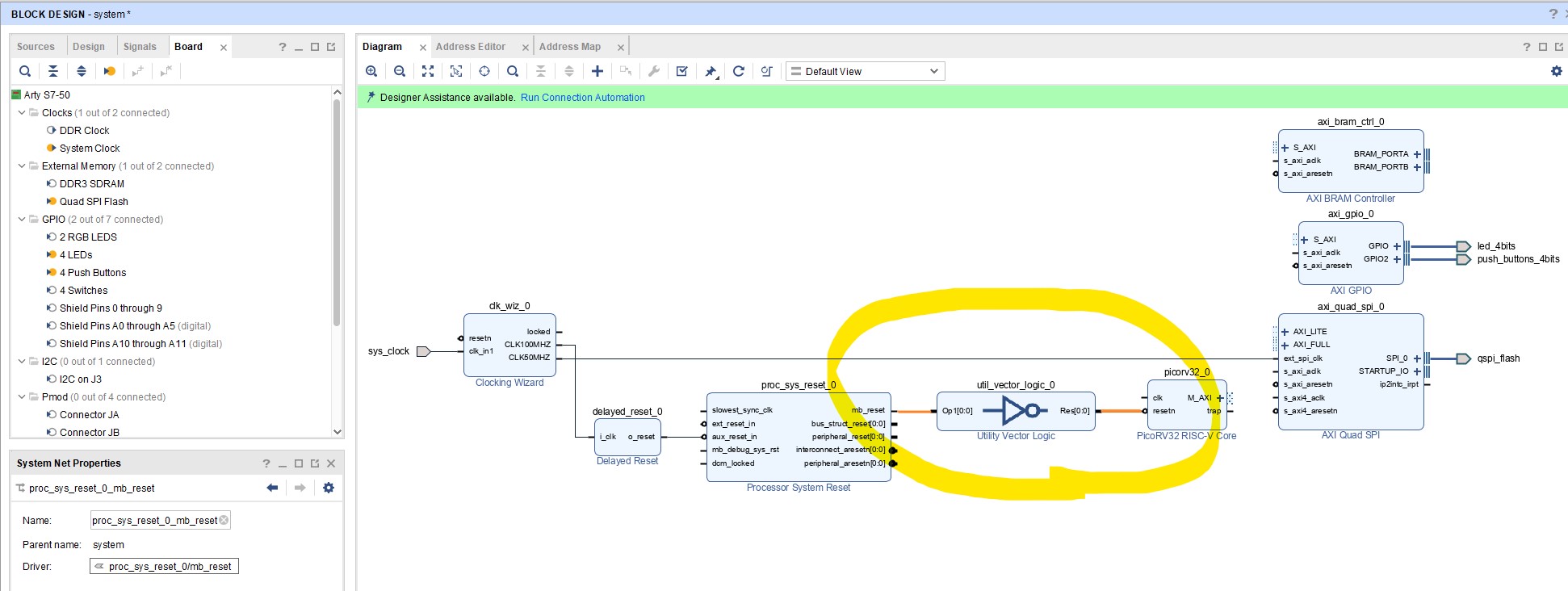
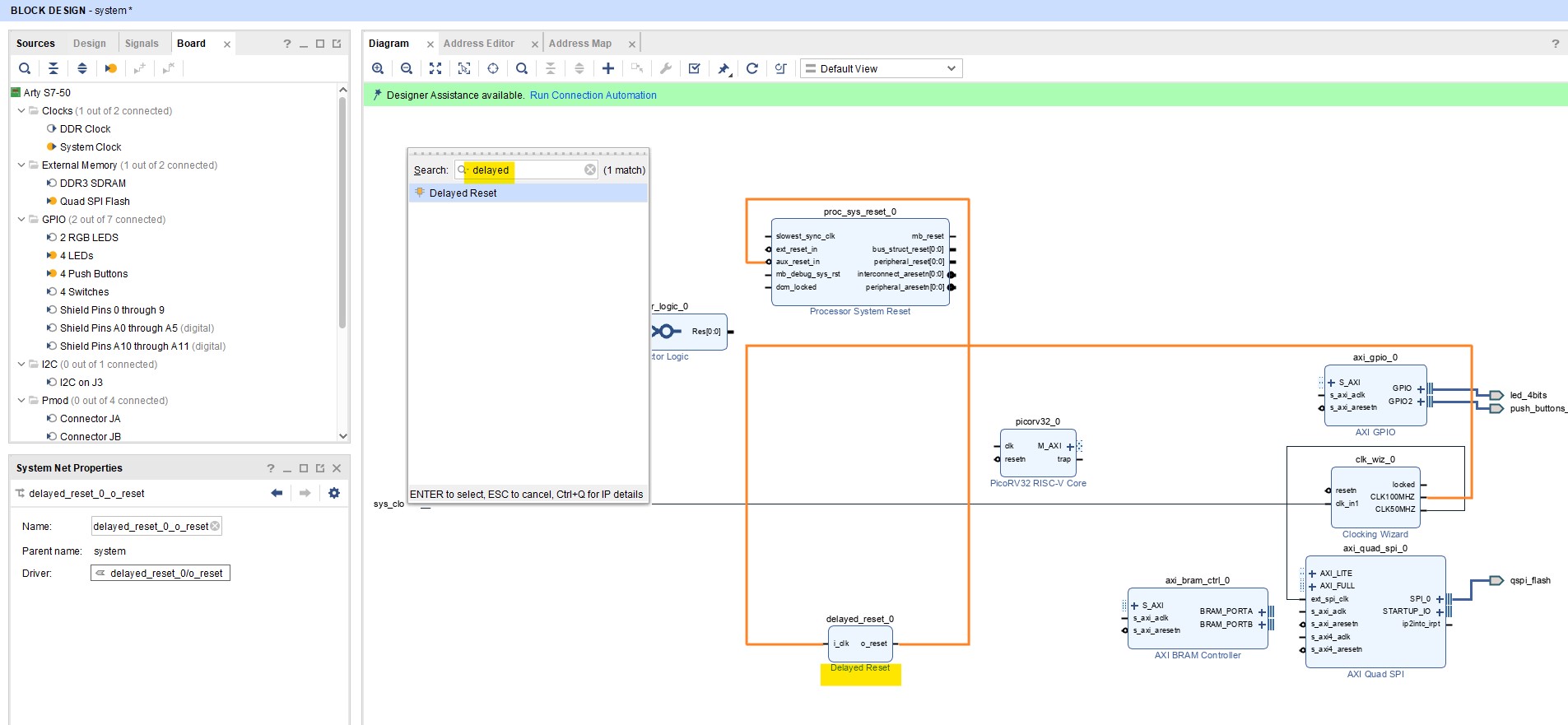
Delayed Reset Pulse
When the Spartan 7 first configures it uses the STARTUPE2 primitive which is connected to the external Flash. We also want to use this flash in XIP mode so we have to supply our own clock signal. After start-up the STARTUPE2 will use the first 2 clock cycles to switch clock domain and these clock pulses will not be passed onto the external flash causing an error. I use a delayed reset pulse to work around this limitation. You can find it HERE. Add this to the design the same way as the PicoRV32 IP and connect the clock signal to the 100MHZ clock and the reset line to the “
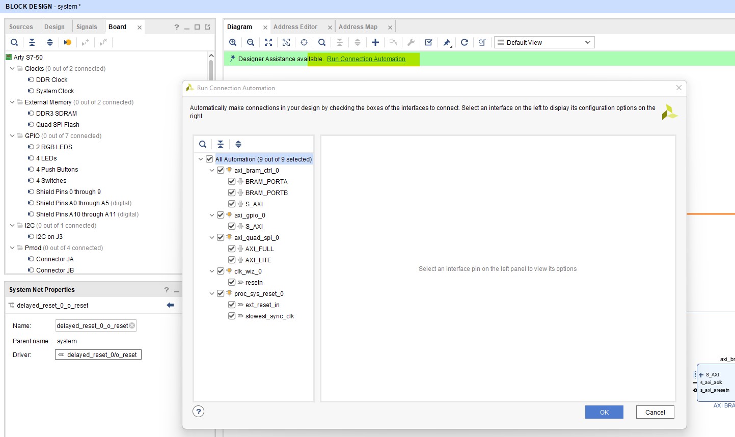
Connection Automation
Now click on “Connection Automation” at the top and select all options.
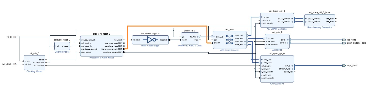
Tidy up
It is likely that Vivado would have connected the “AXI SmartConnect” to the “peripheral_aresetn” pin of the “Processor System Reset” component. Right click the connection on the “AXI SmartConnect” pin and select “Disconnect Pin”. Now connect this reset to the “interconnect_aresetn” pin of the “Processor System Reset” component as shown in the figure to the right.
Address Values
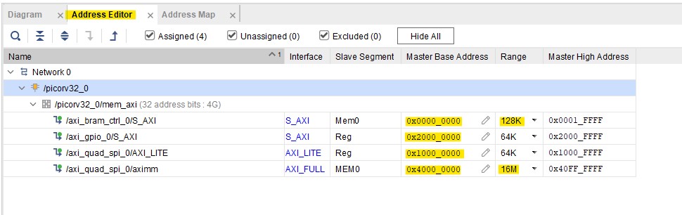
Now open the address tab and set the following values shown in the image to the right.
| /axi_bram_ctrl_0/S_AXI | 0x0000_0000 | 128K |
| /axi_gpio_0/S_AXI | 0x2000_0000 | 64K |
| /axi_quad_spi_0/AXI_LITE | 0x1000_0000 | 64K |
| /axi_quad_spi_0/aximm | 0x4000_0000 | 16M |
Generate Output Products
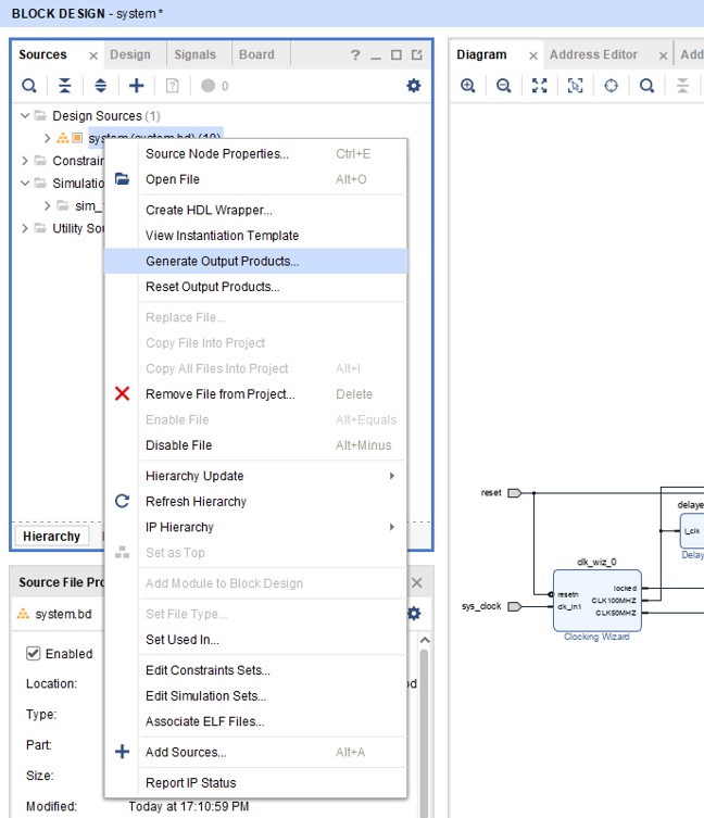
Right click the design in the sources window and select “Generate Output Products”.
Create HDL Wrapper
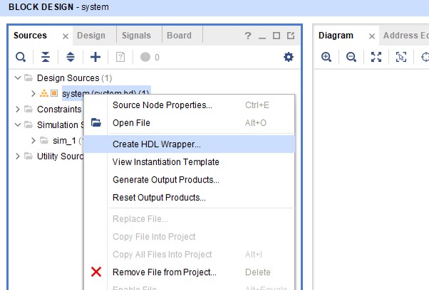
Next right click again on the design and select “Generate HDL Wrapper”, then select the “Let Vivado manage wrapper and auto-update” radio button, hit OK.
Generate Bitstream
Finally all that’s left is to select “Generate Bitstream” in the left-hand-side navigating pane.
Conclusion
We have now created the basis for a PicoRV32 processor with some basic peripherals. Adding more functionality is easy and simply involves adding more components to the design through the same process we just followed, and managing their location in the address space. We can then interact with these components through software by means of their relevant addresses.
