Table of Contents
Introduction
Vapour Phase Soldering has been around for a long time, the earliest reference I can find dates back to 1987. Here, we will explore the theory, try it in practice and look at the results.
With the electronics industry expanding rapidly there is now virtually an IC available for every conceivable use case. Need a motor driver, no problem; need a sophisticated power management controller, no problem, the march of progress is relentless. The miniaturization of components is essential as consumers demand better, faster and more power efficient in smaller and smaller packages.
I’m all for progress, however one undeniable side effect is that we are seeing more and more BGA packages out in the wild. BGA’s are hard to solder at home, you can’t see what’s going on undereneath unless you use sophisticated X-ray machines and you are very much at the mercy of your reflow oven and its capabilities.
While doing research for an “affordable” reflow oven for home/hobby use that can reliably and accurately solder complicated parts, I came to the conclusion that there’s no such a thing. Affordable reflow ovens use IR to heat up the PCB, this works, but IR will favor darker components and cause hot spots on the PCB, a lot of tweaking is required on cheap models to get them to perform optimally. There are also articles online of inadequate grounding on some of the cheaper models and other corner/cost cutting shenanigans.
I wanted to answer the question over whether or not there were alternatives out there other than cheap IR reflow ovens for home/hobby use, that can reliably produce acceptable results. So I set out to see if DIY Vapour Phase Soldering was possible at home.
Steaming PCB’s…
Yeah, that’s a thing now. The idea is to use the LATENT HEAT stored in the vapour of a Galden fluid to heat up the PCB. Simply, energy is required by a medium to change from a liquid to a gas once it has reached boiling temperature. This extra energy does not increase the temperature of the medium it just provides the energy for the phase change, it’s therefore an “invisible” energy. This is why water will remain at a constant 100 °C until it has completely boiled off. This “invisible” energy is called latent heat and it actually stores a lot of energy. Let’s explore this for a second.
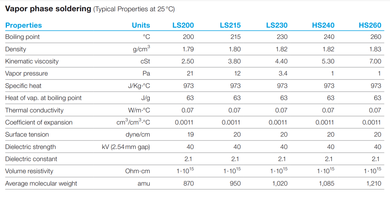
Fig 1 shows us some of the properties of different Galden fluids. For this DIY Vapour Phase Soldering project I use LS230.
The energy required Q to change the phase of a substance of mass m with Lv as the latent heat of vaporization (which we can get from Fig 1), is given by
Q = mLv
So let’s see how much energy is required to convert 1 kg of Galden LS230 from liquid to vapour.
Q = (1kg) x (63kJ/kg) = 63 kJ of energy.
To put that into perpsective the next formula says that 63 kJ is enough energy to heat 1kg of Galden LS230 from 0 to 64 degrees celsius.
ΔEt = m x c x ∆θ
ΔEt is the change in thermal energy, m is mass, c is the specific heat capacity and ∆θ is the temperature change. 63000 / (1 x 973) = 64 oC
As you can see, a substantial amount of energy is involved in the phase change alone. The important thing to note here is that there is NO temperature increase when the phase changes from liquid to gas. When the Galden condenses onto the PCB this energy is released instantly, and so it heats up the PCB. The condensed Galden liquid then returns to the bottom of the container where it boils and the process starts again.
Another key fact to note is the average molecular weight of Galden. Let’s consider Galden LS230 which is what I used. Looking at Fig 1 we can see the amu is 1020. The molecular weight of air is considered to be 29. If we calculate the relative density;
1020 / 29 = 35, we get a value higher than 1.
This means that the Galden vapour is heavier than air and will therefore sink, forming a blanket in the bottom of the container. So unless there is some external disturbance in the airflow your Galden vapour will stay in the bottom of the container and not escape into the atmosphere. This is good news, not least because Galden is expensive, but you also need that vapour blanket around your PCB for the process to work.
The vapour is uniform and doesn’t care about the colour of the components, it will condense everywhere at the same time and uniformly heat up the PCB. This is great, just what we want.
Because the vapour is heavier than air, it displaces the air at the bottom of the container which means optimal wetting and good solder quality due to the oxygen-free environment. Honestly, there is a lot here to get excited about so let’s get to it.
What you will need for DIY Vapour Phase Soldering
- Hot Plate capable of reaching 350 oC
- Borosilicate beaker (Good quality essential) or alternatively a Gastronorm (1/6 size seems adequate for small projects)
- High temperature glass panel (To cover the top)
- Thermocouple
- Galden LS230 (expensive, but it lasts forever)
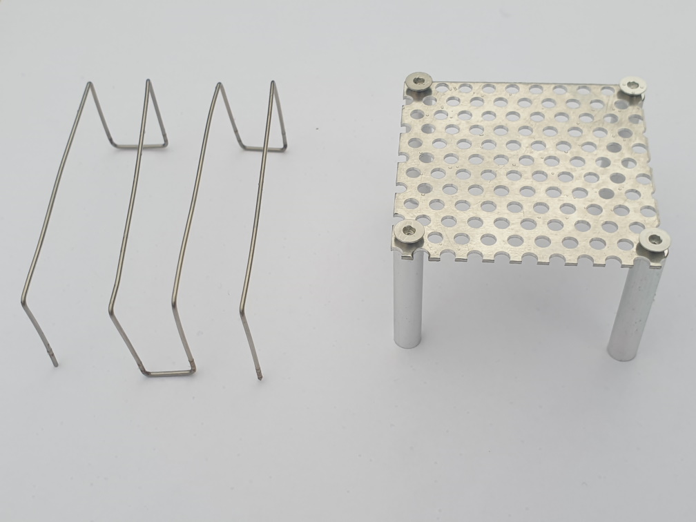
- Piano wire (To make a frame to support your PCB in the bottom of the container)
Process
DIY Vapour Phase Soldering is not difficult or complicated, quite the opposite in fact. Altough it was daunting the first time it is now merely a 15 min exercise to get perfect results every time.
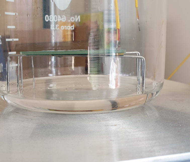
Pour some Galden into the bottom of the container. The exact amount is not important, as long as there are about 5 to 10 mm in the bottom. It will not boil off, later pictures will show the vapor condensing on the sides of the beaker then run down to the bottom.
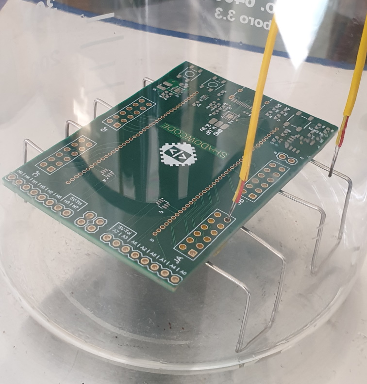
Make a platform out of piano-wire to rest the PCB on. Again the exact height is not important. Around 2 cm is a good starting point. At first, I constructed a platform using aluminium standoffs. This did not work. The aluminium standoffs were way too efficient at conducted heat directly from the bottom of the beaker straight into the PCB and burned it, defeating the purpose of relying on the vapour for heating.
The piano-wire is very thin and does not conduct sufficient heat to negatively affect the process. An even better solution would be to suspend the PCB from the top somehow, maybe with small cables, I haven’t gotten that far yet…
I use a thermocouple with 2 inputs. I place a small piece of kapton tape on the bottom of the PCB to cover one of the 2.54 mm header holes, I then place one of the temp probes into the hole. The probe does not fall through the hole because the kapton tape is blocking the hole at the bottom. I found this an excellent spot to place one of the probes to measure the PCB temperature.
The other probe I dangle in free air around 1 cm above the PCB, for experimental and observational purposes. We will see the temperature rise on both these probes later.
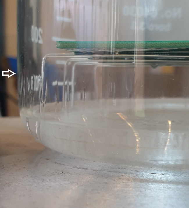
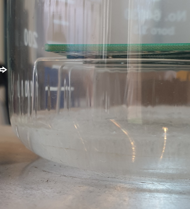
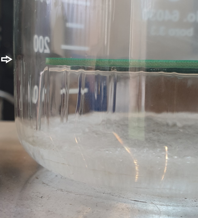
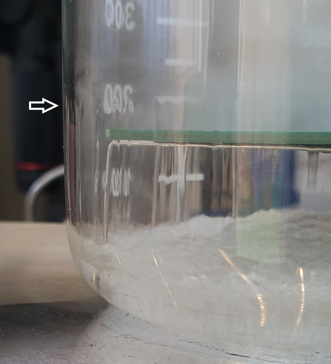
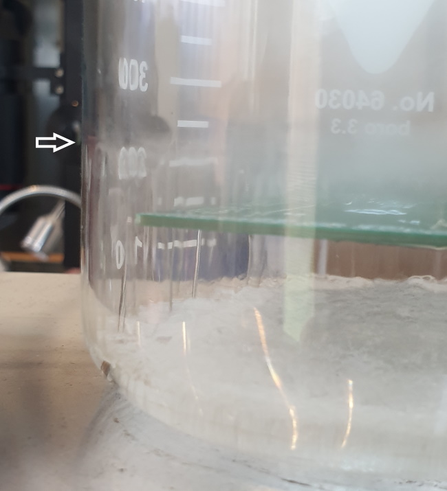
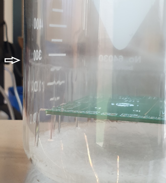
Switch on the hotplate and wait for the Galden to start boiling. It will take a while to get up to 230 °C and then some more time for the vapour blanket to build up and rise to the level of the PCB. Once the vapour reaches the PCB the process happens rather quickly, because, as discussed earlier large amounts of energy are then transferred from the vapour onto the PCB.
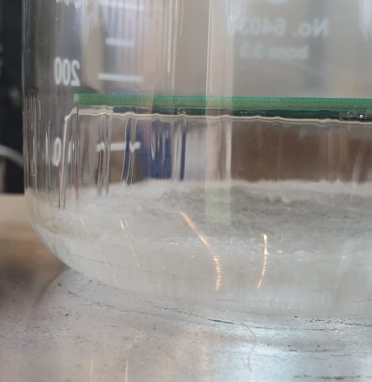
The Galden vapour will also condense on the sides of the beaker then run back down into the bottom. If the amount of Galden vapour that condenses on the sides of the beaker is equal to the amount of Galden vapour produced by boiling, then the system will essentially be in equilibrium and the vapour will not rise higher beyond that point. Here are some images to demonstrate the rising vapour blanket.
So if you decide to do DIY vapour phase soldering at home how much Galden do you sacrifice every time? If you cover the top to prevent external air disturbances I can confidently say that 500ml of Galden will last you a very very long time. How long? Well, that depends on how many projects you solder of course, after 7 projects I cannot see a drop in the level of the Galden in my container.
Ok, so far so good, but what does the temperature profile look like?
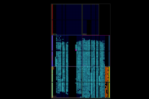
Looking at the temperature profile of our DIY vapour phase soldering we can make some observations. The thermocouple that was hanging in free air, about 1 cm above the PCB lags behind the PCB temperature as expected because the vapour would’ve only risen to this level after it first passed the PCB.
Even though the thermocouple hanging in free air has very low thermal inertia it still peaked at the exact same temperature as the PCB. This proves the theory that the vapour will not heat the object it is condensing on to a temperature higher than what it boiled at, 230 °C in this case, regardless of its mass or colour. The same can be said for the PCB also peaking at 230 °C.
We also observe the sudden 1.85 °C/s rise in temperature from 104 °C at 300s to 224 °C at 365s when the vapour rose to and enveloped the PCB. This is a sharp rise and does not give the PCB enough time to soak as it would during a “normal” reflow profile, however because of the uniform heating by the vapour I have not experienced any issues with this so far. The ramp-down rate of 1 °C/s is perfectly acceptable.
Results
So what do the final soldering results of my DIY Vapour Phase Soldering project look like? I’ll let you decide…
Disclaimer
If you decide to give this a go then please do take care. Remove your pets and your children from the room and wear suitable protective equipment. I have not had any issues but its always better to be safe than sorry. DIY Vapour Phase Soldering at home is an effective way to solder small BGA components and also board with a mixture of diffenerent component sizes.
If you decide to give this a go let us know in the comment section your experiences and tips for improvement.